
Why Does My Braking Chopper Keep Burning Out Resistors Under Heavy Deceleration
2026-09-04
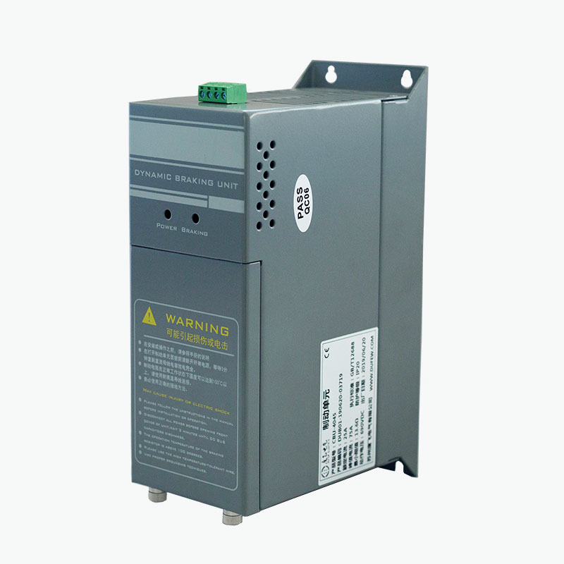
If you operate variable frequency drives (VFDs) in high-inertia applications—such as centrifuges, downhill conveyors, or large fans—you have likely faced this costly frustration: a Braking Chopper that functions perfectly during light loads but repeatedly destroys its resistor bank when decelerating heavy masses. At Dufew, we have diagnosed hundreds of such failures across industrial sites, and the root cause is rarely a single faulty component. Instead, it is a systemic mismatch between thermal dynamics, control logic, and mechanical duty cycles. This article dissects the technical reasons behind resistor burnout and provides actionable solutions grounded in power electronics and thermodynamics.
The Physics of Regenerative Energy: Why Your Resistor Overheats
During rapid deceleration, the motor becomes a generator, pumping regenerative energy back into the DC bus. The Braking Chopper acts as a protective switch that shunts this excess voltage into a dynamic braking resistor (DBR), dissipating energy as heat. The chopper itself does not burn the resistor—the thermal accumulation does. Each braking event deposits a fixed amount of energy (joules) into the resistor mass. If the interval between braking cycles is shorter than the resistor’s cool-down time, the baseline temperature rises with every stop. Eventually, the resistor element exceeds its maximum hot-spot temperature (typically 350–450°C for wire-wound types), causing oxidation, hot spots, and eventual open-circuit failure.
Common Failure Modes vs. Diagnostic Indicators
The table below maps observable symptoms to their most probable engineering causes, helping you move beyond trial-and-error replacements.
| Symptom | Likely Root Cause | Verification Method |
|---|---|---|
| Resistor physically cracked or glowing red | Peak power exceeds rated instantaneous wattage | Measure DC bus voltage during deceleration; compare with resistor ohmic value (P = V²/R) |
| Resistor fails after 2–3 consecutive fast stops | Insufficient continuous power rating (duty cycle mismatch) | Log braking duration and pause intervals; calculate RMS power over a 5-minute window |
| Chopper IGBT intact, resistor still burnt | Chopper ON-time too long (switching frequency < optimal) | Inspect chopper firing pattern with an oscilloscope; check for stuck PWM signal |
| Resistor fails randomly, not under max load | Loose termination or corroded connections increasing local resistance | Thermal imaging of terminal blocks during braking |
| Multiple resistors in parallel—only one burns | Unequal current sharing due to mismatched resistance values | Measure each resistor leg with a micro-ohmmeter; tolerance should be within ±5% |
The Critical Role of Chopper Control Strategy
Most standard Braking Chopper modules use a fixed threshold voltage (e.g., 390 V DC for a 230 V AC system, or 780 V DC for 460 V). However, heavy deceleration creates a voltage spike that rises faster than the chopper can respond. If the chopper’s hysteresis band is too wide, it waits until the DC bus reaches the upper trip point, then dumps a massive current pulse into the resistor. That pulse may be 3–5 times the resistor’s design current, even if the average power seems acceptable. At Dufew, we recommend selecting a chopper with adjustable threshold and variable switching frequency, allowing you to spread the braking energy over a longer time window—reducing peak stress without extending total stopping distance.
Sizing Methodology: A Step-by-Step Calculation
To determine whether your existing resistor is under-sized, follow this engineering workflow:
-
Calculate kinetic energy – �=12��2 (J = total inertia reflected to motor shaft, ω = angular speed).
-
Determine braking power – �����=�/������, where ������ is your desired deceleration time.
-
Select resistor ohmic value – �=�����2/����� (V_trip = chopper activation voltage).
-
Verify continuous rating – �����=�����×duty factor (braking time / total cycle time).
-
Apply a safety margin – Always add 20–30% to both peak and continuous ratings for unaccounted friction variations.
A common oversight: using a resistor with adequate continuous wattage but insufficient thermal mass (heat capacity). Two resistors with the same wattage can have vastly different cooling time constants based on their core material and fin design.
Frequently Asked Questions About Braking Chopper Failures
Q: Can a failing DC bus capacitor cause my Braking Chopper to burn resistors more frequently?
A: Yes, and this is frequently overlooked. Aged capacitors lose capacitance and increase equivalent series resistance (ESR), which leads to higher ripple voltage on the DC bus. The Braking Chopper interprets that ripple as a rising DC level, causing it to trigger earlier and more often than intended. This premature activation subjects the resistor to additional thermal cycles that are not related to actual regenerative energy. We advise measuring capacitance and ESR during every preventive maintenance interval—if the capacitance has dropped by more than 15% from its nameplate value, replace the capacitor bank before changing the resistor.
Q: Is it better to use a higher resistance value to reduce current through the Braking Chopper?
A: Counterintuitively, a higher resistance reduces current (I = V/R) but increases the time required to dissipate the same amount of energy. If the resistance is too high, the DC bus voltage may not drop below the chopper’s turn-off threshold before the next braking event, causing the chopper to remain active continuously—this is called “chopper saturation.” Under saturation, the resistor sees a near-constant DC current, which generates more total heat than short, high-current pulses. The optimal resistance is the one that brings the DC bus down to the lower hysteresis limit within 80% of your available deceleration time. Use the formula ��������=�����×������/(����×Δ�), where C_bus is the total DC link capacitance.
Q: How does ambient temperature and enclosure ventilation affect the Braking Chopper resistor lifespan?
A: Resistor power ratings are specified at 25°C ambient. For every 10°C rise above that, the continuous power handling derates by approximately 5–8%. In a sealed IP54 enclosure without forced airflow, internal temperatures can exceed 60°C, effectively reducing a 10 kW resistor to a 7 kW unit. Additionally, hot air recirculation traps heat around the resistor, increasing its baseline temperature. At Dufew, we mandate a minimum clearance of 150 mm around all braking resistors and recommend thermostatically controlled fans for any application with more than two braking events per minute. Always measure the internal enclosure temperature under full load—if it surpasses 50°C, upgrade to a larger resistor with a higher thermal class (Class H, 180°C rated insulation).
Practical Countermeasures for Immediate Implementation
-
Install a resistor thermal switch – This cuts power to the chopper if the resistor exceeds a safe temperature, preventing catastrophic burnout while flagging an alarm.
-
Increase deceleration time – Extending the ramp-down from 2 seconds to 4 seconds halves the peak power, drastically reducing thermal shock.
-
Parallel two resistors with individual fuses – This provides redundancy and equalizes current if each leg has its own series inductor to balance impedance.
-
Upgrade to a chopper with adaptive threshold – Models with dynamic voltage tracking adjust the trip point based on actual motor slip, reducing unnecessary activations.
When to Replace vs. Retrofit
If your application demands frequent heavy braking (e.g., crane hoisting or test bench dynos), a standard Braking Chopper with a passive resistor may never deliver satisfactory life. In such cases, consider retrofitting to a regenerative drive that feeds energy back to the mains—but this requires a clean power grid and harmonic filters. For most plants, the more economical path is a properly sized chopper-resistor pair with active thermal management. Dufew offers a full range of Braking Chopper modules with integrated temperature monitoring and customizable switching algorithms, designed specifically for cyclic high-torque deceleration.
Contact Us for a Free Braking Energy Audit
Resistor burnout is not an unavoidable maintenance cost—it is a design oversight that can be corrected with accurate inertia measurement, correct component selection, and proper enclosure cooling. Dufew provides onsite thermal profiling and chopper parameter tuning for heavy industrial drives. Our engineering team will analyze your existing deceleration profile, compute the true RMS braking power, and recommend a drop-in solution that extends resistor life by 3–5 times. Do not wait for the next production stop. Reach out to us today through our website or call your local Dufew representative to schedule a no-obligation diagnostic review. Your uptime is our priority.