

What Role Do Material Choices Play in the Performance of Rigid-Flex Boards
2026-03-10
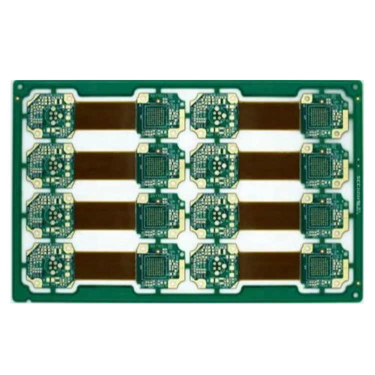
When engineering high-reliability electronics, the performance of Rigid-Flex Boards hinges critically on material selection. At Akeson, we understand that the substrate, adhesive, and copper type determine not only electrical integrity but also mechanical durability. Choosing the wrong materials can lead to delamination, signal loss, or premature failure in the field.
Why Material Composition Dictates Reliability
Rigid-Flex Boards combine hardboard sections with flexible circuit layers. This hybrid structure demands materials that can withstand repeated bending while maintaining signal integrity. The rigid sections typically use FR4, while flex layers rely on polyimide films. The adhesive system—acrylic, epoxy, or adhesive-free—affects thermal stability and flex life.
Key Material Properties to Evaluate
| Material Property | Impact on Performance | Common Choices |
|---|---|---|
| Dielectric Constant | Signal speed & impedance control | Polyimide, FR4 |
| Flexural Endurance | Bending cycle life | Adhesive-free laminates |
| Thermal Stability | Soldering & operating range | High-Tg FR4, Polyimide |
| Moisture Absorption | Reliability in humid environments | Low-flow prepregs |
How Material Choices Impact Specific Performance Areas
The copper type used in Rigid-Flex Boards—rolled annealed versus electrodeposited—directly affects flex life. Rolled annealed copper offers superior elongation, making it ideal for dynamic flex applications. Coverlay materials protect flex circuits from contamination; polyimide coverlays with acrylic adhesives provide a balance of flexibility and environmental resistance.
Common Material-Related Failures
-
CAF Growth: Occurs with poor resin systems in rigid sections
-
Adhesive Weeping: Excess flow during lamination causing contamination
-
Impedance Variation: Caused by inconsistent dielectric thickness
Rigid-Flex Boards FAQ
What is the best material for high-frequency rigid-flex applications?
For high-frequency designs, low-loss materials like modified polyimide or LCP are recommended. These materials maintain a stable dielectric constant across the frequency range and exhibit low dissipation factor, minimizing signal loss. The rigid sections should use high-frequency laminates like Rogers material, while the flex areas utilize low-Dk polyimide. Akeson recommends adhesive-free laminates for improved signal performance in RF applications.
How do material choices affect the minimum bend radius of a rigid-flex board?
The minimum bend radius is directly tied to the flex layer thickness and copper type. Thinner polyimide cores and rolled annealed copper allow for tighter bend radii. A general rule is to maintain a bend radius at least 10 times the flex stack thickness for dynamic applications. Using thicker adhesives or ED copper increases the minimum safe radius and can lead to conductor cracking under repeated flexing.
Why is the adhesive system important in rigid-flex material selection?
The adhesive bonds the copper to the polyimide and bonds layers together. Acrylic adhesives offer good flexibility but lower thermal resistance. Epoxy adhesives provide better thermal performance but can be brittle. Adhesive-free laminates, where copper is directly bonded to polyimide, offer the highest thermal stability and flex life but at a higher cost. The choice impacts Z-axis expansion and resistance to delamination during assembly.
Optimizing Performance Through Material Science
Advanced material combinations allow Rigid-Flex Boards to meet demanding military, medical, and automotive standards. Using no-flow prepregs in rigid sections prevents resin from flowing onto exposed flex areas during lamination. Selecting materials with matched CTE reduces stress on plated through-holes during thermal cycling.
Akeson engineers evaluate your specific application—whether it requires dynamic flexing, high-temperature operation, or tight impedance control—to specify the optimal material set for your Rigid-Flex Boards.
Partner with Akeson for Expert Material Selection
Choosing the right materials for your Rigid-Flex Boards is a complex engineering decision. Work with a partner who understands the science behind the stack-up.
Contact us today to discuss your project requirements and receive a material recommendation tailored to your performance needs.