
What Are the Common Failure Modes of Electrical Measuring Instruments PCB
2026-09-18
Electrical Measuring Instruments PCB play a critical role in ensuring accurate readings, stable performance, and long-term reliability across industrial, laboratory, and field applications. At Aisen, we have seen how even minor PCB defects can lead to measurement drift, signal loss, or complete instrument failure. Understanding the most common failure modes helps engineers design more robust boards and avoid costly downtime.
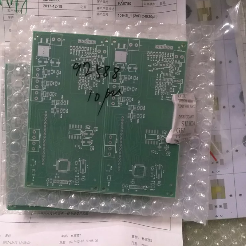
1. Solder Joint Fatigue and Cracking
Solder joints are among the most vulnerable points on an Electrical Measuring Instruments PCB. Thermal cycling, vibration, and mechanical stress cause microcracks that gradually increase contact resistance. In precision instruments, this often appears as intermittent readings or offset errors.
| Cause | Symptom | Prevention |
|---|---|---|
| Thermal cycling | Intermittent signal | Use compliant solder alloys |
| Vibration | Cracked joints | Add conformal coating |
| Poor wetting | High resistance | Optimize reflow profile |
Aisen recommends rigorous thermal shock testing before mass production.
2. Conductive Anodic Filament (CAF) Growth
CAF is a electrochemical migration failure inside the Electrical Measuring Instruments PCB substrate. It occurs when moisture and voltage combine to grow conductive filaments between copper traces, leading to leakage currents and short circuits.
| Factor | Risk Level | Mitigation |
|---|---|---|
| High humidity | High | Use low-CTE laminates |
| Tight trace spacing | Medium | Increase spacing |
| Contaminated laminate | High | Source from qualified suppliers |
Aisen applies strict material verification to reduce CAF risk.
3. Delamination and Popcorning
Delamination happens when layers of the Electrical Measuring Instruments PCB separate due to absorbed moisture during soldering. Popcorning is a visible form of this failure. Both degrade impedance control and mechanical integrity.
| Cause | Effect | Solution |
|---|---|---|
| Moisture absorption | Layer separation | Bake before assembly |
| High reflow temp | Internal cracks | Use proper ramp rates |
| Poor lamination | Weak bonds | Audit PCB supplier |
Aisen uses vacuum lamination and controlled storage to prevent this.
4. Electromigration and Corrosion
Corrosion and electromigration degrade fine traces on Electrical Measuring Instruments PCB, especially in high-impedance measurement circuits. Flux residue, humidity, and bias voltage accelerate these failures.
| Trigger | Result | Prevention |
|---|---|---|
| Flux residue | Leakage current | Clean after assembly |
| Humidity | Trace corrosion | Conformal coating |
| DC bias | Metal migration | Reduce voltage stress |
Aisen incorporates cleanliness validation and coating standards.
5. Component Degradation and Pad Lifting
Repeated rework, thermal stress, or poor pad design causes pad lifting and component degradation. This is common in Electrical Measuring Instruments PCB used in field calibration equipment.
| Cause | Symptom | Fix |
|---|---|---|
| Excessive rework | Lifted pads | Improve pad size |
| Thermal stress | Cracked capacitors | Use AEC-Q200 parts |
| Poor adhesion | Open circuits | Plasma treatment |
Aisen designs pads with enhanced anchorage for high-reliability use.
FAQ: Electrical Measuring Instruments PCB
Q: What is the most common failure mode of Electrical Measuring Instruments PCB?
A: Solder joint fatigue is the most frequent, caused by thermal cycling and vibration, leading to intermittent or drifting measurements.
Q: How can I prevent CAF failure in Electrical Measuring Instruments PCB?
A: Use low-moisture laminates, increase trace spacing, control humidity during storage, and choose qualified materials from trusted suppliers like Aisen.
Q: Does conformal coating really improve Electrical Measuring Instruments PCB reliability?
A: Yes, conformal coating protects against moisture, corrosion, and electromigration, significantly extending the service life of Electrical Measuring Instruments PCB in harsh environments.
Conclusion
Failure modes in Electrical Measuring Instruments PCB are preventable with proper design, material selection, and manufacturing controls. Aisen delivers high-reliability PCB solutions for precision measurement applications, ensuring your instruments perform accurately and consistently.
Contact us today to discuss your Electrical Measuring Instruments PCB requirements and get a tailored solution from Aisen.